In this post, I will show how I created my character model.
The first step was to model half of the character using a humanoid image on a "Frozen" plane as a reference image to get the basic shape. (The plane setup was demonstated in my first blog post for my prop.)
So assuming you know how to set that up, I shall continue.
 |
| Image 1 |
Firstly, I started using primitive shapes to make up the basic structure of my humanoid creature. I used cylinders which were then converted to editable poly's for the arm, leg and torso (Image 1) I then began tweaking the parts to line up with the reference images (image 2). The best way I found to do this, was to edit the vertices. I often applied the "Mirror" modifier found on the Modify pane on the right. This gave me an idea of how the final mirrored model would turn out, allowing me to edit the width/height of the half I was working until it looked right.
 |
| Image 2 |
 |
| Image 3 |
After a few tries I had gotten the model to look how I wanted. I changed the human legs to reverse-jointed and also added a clawed hand. After trying to mirror the image, I noticed that the knees overlapped. This was corrected by dragging the hips farther out to the side of the model by selecting the "faces" option (hotkey - 4) on the modify pane and dragging the selection box to the part of the leg I needed to move. (Holding ctrl and clicking the faces that I missed was very useful).
 |
| Image 4 |
As shown in image 4, the model now looked proportionally correct so I create a copy of the image (shift & drag) and then mirrored it. The model and it's modifiers were then collapsed by right clicking the editable poly in the side pane and clicking "Collapse All". Between the thighs I had to "cap" and "bridge" certain parts so no gaps were present.
 |
| Image 5 |
I then applied the "mesh smooth" modifier (found in the modifier drop down menu above the editable poly selection) to the model which I could keep referencing whenever I altered something to see how it will look at the end. I also gave the creature a more life-like stance as shown above in image 5.
 |
| Image 6 |
I then began working on the creatures head. I started with a "Sphere" primitive shape and scaled the bottom half of the object as shown in image 6.
 |
| Image 7 |
I widened the top of the head and narrowed the "Jaw" area giving the model quite an alien feel to it. The bottom of the head was also widened to connect to the shoulders of the main body.
 |
| Image 8 |
The eyes were created using elongated spheres which I then attached to the head after positioning them in the right place.
 |
| Image 9 |
The claws for the feet were the last parts that were needed to be added using a separate object. I started with cubes and then brought them to a point at the end and also indenting the vertices into the model on the underside of the claw to show they would be used for digging/clinging to surfaces.
 |
| Image 10 |
For the tail, I extruded one of the faces that was still visible after I bridged the gaps after mirroring the original model. To extrude, you must select the "Faces" option on the Modify pane and click "Extrude" under the Edit Polygons menu. This was a perfect flat surface to create the tail with. Each new part that was extruded was made thinner until the tail reached a point.
 |
| Image 11 |
The model needs to now be "unwrapped". The previous blog for the prop demonstrates how this is done. Once the model is unwrapped using the "Unwrap UVW" modifier, the image is saved as a .tiff file and edited in photoshop as shown below.
 |
| Image 12 |
 |
| Image 13 |
 |
| Image 14 |
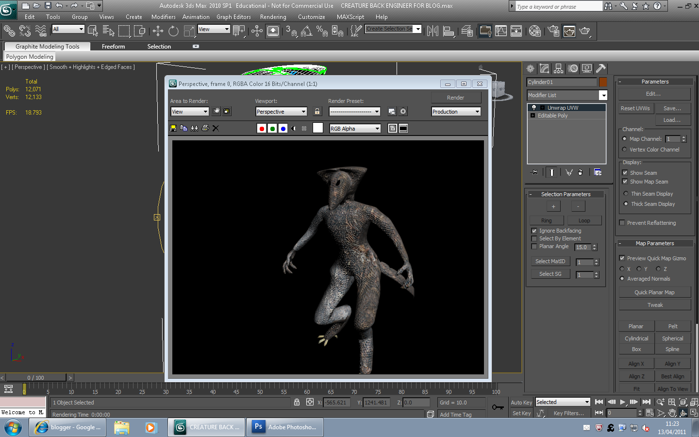
Lastly, the model needs the texture applied to it. Open the material editor menu (Default key - M) and the above menu appears. One of the grey spheres needs to be selected and the "Diffuse Colour" box under "Maps" has to be checked. The box to the right of Diffuse Colour should then be clicked which brings up another menu with the "Bitmap" option being at the top. Double click the bitmap option and then open the .tiff file that was edited in photoshop. The options "Go to Parent" and then "Show standard map in Viewport" located directly below the spheres on the "Material Editor" menu must be selected respectively.
Now the image applied to the sphere can be dragged onto the model as shown below.
 |
| Image 15 |


No comments:
Post a Comment