Wednesday 25 May 2011

Unit 65 - Animation

Jumping animation blog


Using the Cryptic AR rig, I began to move certain parts of the body with different frames selected. After the movement for that section is finalized, I select all the parts (ctrl + a) and check the box in the bottom right corner - "Set Key" and the click the key icon to the left of "Set Key" to create a Key frame. The program then fills in the movements between the keyframes. "Auto Key" is another option. This creates the key frames automatically and a menu can be opened up to alter the paths of the animations. It is quite useful for simpler animations but as there are many different movements in a humanoid animation, much more detail is required and thus, the "Set Key" option would be a better choice.

Below, you will see a number of screenshots that will show each keyframe in order which shows how I created my animation.


Below is a youtube video of my animation.


Monday 16 May 2011

Modeling my Environment

 Firstly for my environment, I need a room outline. I created this using a cube primitive and making it an editable poly. After this, I selected the button "Flip" under Edit Elements, making the sides that are being viewed from the outside, transparent so the inside of the "room" can be viewed as shown above.


Now I added a number of other primitives. This is described in much more detail earlier on in my blog so I shall assume that the previous entries have been viewed before this one.

 As you may notice above, I have added a boolean to a few of the objects such as the light blue "machine" and the room in the corner. A boolean basically removed a shape that is overlapping another shape and also cuts out any part of the shape the previously removed shape was touching. This can be used to create doors and gaps in objects. To boolean an object, firstly you must connect two shapes together; one shape being the one you want to stay in on the model (we will call this object A) and one that will be removed (Object B), taking a section of the remaining shape with it. Now, on the "Create" tab, you need to select "Compound Objects" from the dropdown box below and then select the "Boolean" box under object type. With object A selected, click the box "Pick operand B" and select object B. Object B should now have disappeared, taking part of A with it creating a hole in the object.


Now I started to add more details such as power generators and conveyor belts.


The method used to UV Unwrap in previous blogs was then used. But to make this texturing a lot easier this time, I broke the model into parts and unwrapped them in smaller groups as opposed to unwrapping the whole thing. Firstly I unwrapped the walls, floor and ceiling, the power generators, the machine, sub walls and conveyor belt. As before, they were then all saved as a .tif file and textured using adobe photoshop.

After the textures were done, or I wanted to check how they looked, the file was saved and then applied to the model using the "material editor".

The textures I used were from the website cgtextures.com

This texturing method took me roughly 2 hours (including unwrapping) and finally the environment was finished as shown below.


Monday 18 April 2011

Modeling my character

In this post, I will show how I created my character model.

The first step was to model half of the character using a humanoid image on a "Frozen" plane as a reference image to get the basic shape. (The plane setup was demonstated in my first blog post for my prop.)

So assuming you know how to set that up, I shall continue.


Image 1


Firstly, I started using primitive shapes to make up the basic structure of my humanoid creature. I used cylinders which were then converted to editable poly's for the arm, leg and torso (Image 1) I then began tweaking the parts to line up with the reference images (image 2). The best way I found to do this, was to edit the vertices. I often applied the "Mirror" modifier found on the Modify pane on the right. This gave me an idea of how the final mirrored model would turn out, allowing me to edit the width/height of the half I was working until it looked right.
Image 2


Image 3


 After a few tries I had gotten the model to look how I wanted. I changed the human legs to reverse-jointed and also added a clawed hand. After trying to mirror the image, I noticed that the knees overlapped. This was corrected by dragging the hips farther out to the side of the model by selecting the "faces" option (hotkey - 4) on the modify pane and dragging the selection box to the part of the leg I needed to move. (Holding ctrl and clicking the faces that I missed was very useful).

Image 4
As shown in image 4, the model now looked proportionally correct so I create a copy of the image (shift & drag) and then mirrored it. The model and it's modifiers were then collapsed by right clicking the editable poly in the side pane and clicking "Collapse All". Between the thighs I had to "cap" and "bridge" certain parts so no gaps were present.

Image 5
 I then applied the "mesh smooth" modifier (found in the modifier drop down menu above the editable poly selection) to the model which I could keep referencing whenever I altered something to see how it will look at the end. I also gave the creature a more life-like stance as shown above in image 5.
Image 6

I then began working on the creatures head. I started with a "Sphere" primitive shape and scaled the bottom half of the object as shown in image 6.
Image 7


I widened the top of the head and narrowed the "Jaw" area giving the model quite an alien feel to it. The bottom of the head was also widened to connect to the shoulders of the main body.

Image 8
 The eyes were created using elongated spheres which I then attached to the head after positioning them in the right place.
Image 9


The claws for the feet were the last parts that were needed to be added using a separate object. I started with cubes and then brought them to a point at the end and also indenting the vertices into the model on the underside of the claw to show they would be used for digging/clinging to surfaces.

Image 10
 For the tail, I extruded one of the faces that was still visible after I bridged the gaps after mirroring the original model. To extrude, you must select the "Faces" option on the Modify pane and click "Extrude" under the Edit Polygons menu. This was a perfect flat surface to create the tail with. Each new part that was extruded was made thinner until the tail reached a point.

Image 11


The model needs to now be "unwrapped". The previous blog for the prop demonstrates how this is done. Once the model is unwrapped using the "Unwrap UVW" modifier, the image is saved as a .tiff file and edited in photoshop as shown below.

Image 12

Image 13

Image 14

Lastly, the model needs the texture applied to it. Open the material editor menu (Default key - M) and the above menu appears. One of the grey spheres needs to be selected and the "Diffuse Colour" box under "Maps" has to be checked. The box to the right of Diffuse Colour should then be clicked which brings up another menu with the "Bitmap" option being at the top. Double click the bitmap option and then open the .tiff file that was edited in photoshop. The options "Go to Parent" and then "Show standard map in Viewport" located directly below the spheres on the "Material Editor" menu must be selected respectively.

Now the image applied to the sphere can be dragged onto the model as shown below.

Image 15


Monday 21 March 2011

Modeling my Prop

Firstly I created 2 planes, one for the front and one for the side of the model. I then obtained 2 images to fit both planes respectively. I did this by selecting the “plane” tab and placing them in both front and side perspectives. To add the image to the plane you press the default “Material Editor” key – M. This brings up the menu below. Then open the sub menu “Maps”, check the box “Diffuse Colors” and then click the box “None” next to the diffuse color box. Then double click the bitmap option and then open the image in the windows explorer tab that pops up. Now click “go to parent” and then “show standard map in viewport”. The image can then be dragged onto the object or plane in this case as shown. This is how to apply a texture to an object.


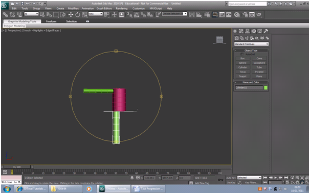
Now that the reference planes are done, it is pretty straight forward from here. Extrusion modeling is the best way, in my opinion, to create a prop, especially one made of fairly simple shapes like a pistol. Starting off as shown below, with some primitive shapes such as boxes, you need to fill in the main part of the gun using the side view reference plane.


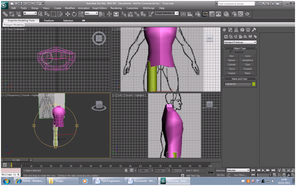
Convert the basic shape to an editable poly first, and then start extruding the front of the object as shown above to fill in the right areas. The vertices and edges should be dragged certain parts to create curves similar to those shown on the reference image.

After the basic shape is completed from extrusions, you must make the shape see-through so you can edit the shape to become much more detailed as you can see the reference image through the model. Once the model is suitable (I changed a few parts of the model as I didn't like some parts of the reference image) you can convert the image back to opaque.


I then split the model right down the middle into two halves. I deleted one as once I finish texturing one side of the gun, I will mirror the image so both sides are similar textures.


Next I had to unwrap the model so I could see which parts I was going to texture. With the model selected, I chose the Modifier "Unwrap UVW" and the above screen appeared. The blue area around all of the green lines must contain all of the green. In the meantime, I arranged different faces of the model, separating it into location such as the handle faces in one area, and textures such as every part that was going to have the same texture as the grip. After all of the faces were in a suitable place inside the blue box, I then select the option under Tools, "Render UVW Template..."

Click Render UV Template when the above window appears and save it as a .png file. This can then be opened in photoshop. The resulting image shown below has the guidelines of the faces from the previous unwrapping step. Any colour/texture applied within these lines will appear on the 3dsmax model when it is saved.

Once the image is completely textured or you just want to check progress of the texture on the model, you must save the photoshop file as a .tif. Using the same method as was used to apply the image to the planes, (Material editor < Maps < Diffuse color < Bitmap < Select image < Go to Parent < Show standard map in viewport - then drag the image to the model) apply the .tif image to the model. This will now update everytime you save the photoshop file after making alterations and then click the render button in 3dsmax.


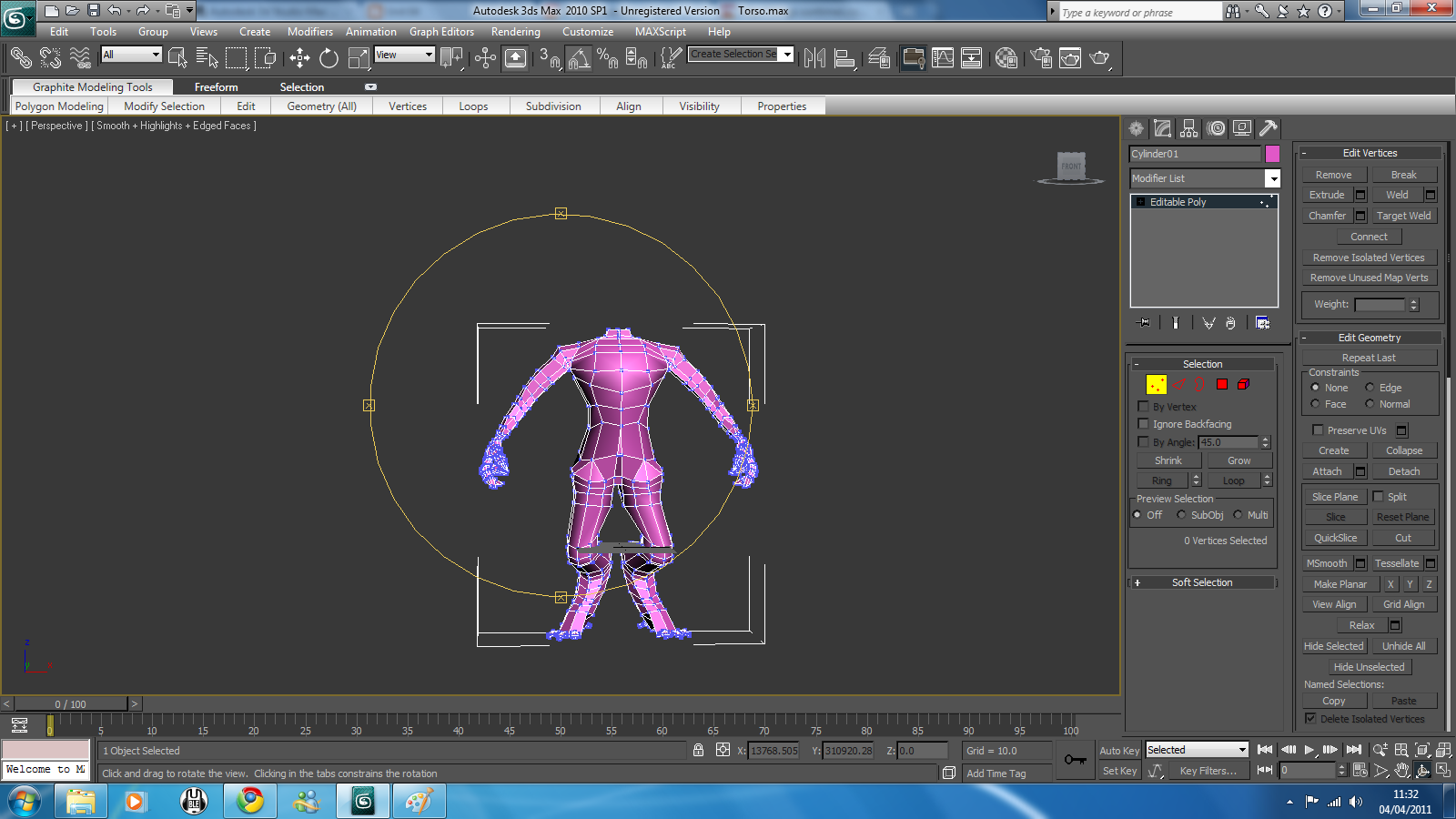
After the texturing is finished, I then clone the current model and apply a mirror modifier along the z-axis and move both sides as close as possible. Using "Front view" I select all the vertices along the centre of the model and then click "Weld" to join them all together shown below.


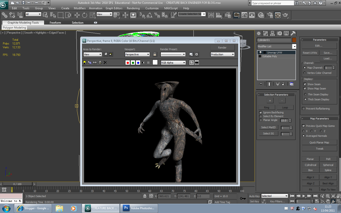
The model should now be finished. To check the final render, click the render icon at the top right.


Followers